Skip to content

How to Choose the Right Tapered Motor Shaft?

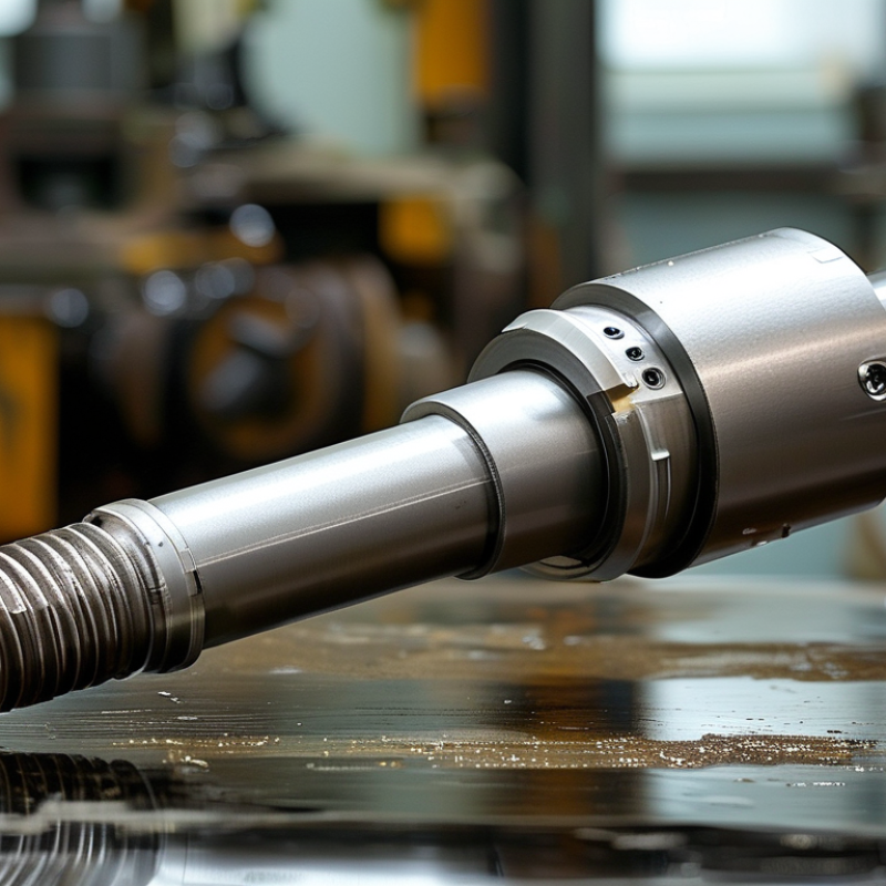
Choosing the right Tapered Motor Shaft begins with more than matching a catalog diameter. Torque, rotational speed, taper angle, keyway design, and mounting space must work together. A shaft that fits the motor may still create vibration, slippage, or premature bearing wear.

Richard G. Budynas, a respected mechanical-design authority, writes, “A shaft is a rotating member, usually of circular cross section, used to transmit power or motion.” This principle remains practical when evaluating tapered designs. The shaft must transfer power reliably while maintaining accurate alignment under real operating loads. Measure the bore, exposed length, shoulder position, and allowable runout. Even a small dimensional error can become visible at high speed.

Look closely at the working environment. Dust, moisture, heat, and frequent reversing can change the best material or surface treatment. A hardened steel shaft may suit heavy torque, while stainless steel can be more appropriate near corrosive washdown areas. Do not ignore installation details. A clean taper, correct locking hardware, and proper torque can prevent costly movement during operation.

The perfect choice rarely exists. Trade-offs remain. A larger shaft may improve strength but reduce available clearance. A tighter fit may improve stability but complicate maintenance. This guide examines each decision with practical measurements, engineering reasoning, and realistic limitations, helping readers choose a Tapered Motor Shaft that performs reliably beyond the specification sheet.

How to Choose the Right Tapered Motor Shaft?

Define Load and Duty: IEC 60034-1 Ratings and S1 Continuous Operation

How to Choose the Right Tapered Motor Shaft?

A tapered motor shaft should match the real load, not only the catalog power. Record torque, speed, starting frequency, inertia, and radial or axial forces. These details influence shaft stress and bearing life. In field checks, I often find that the coupling fits correctly, but the actual load exceeds the original estimate. That mistake is expensive.

IEC 60034-1 ratings provide a consistent basis for evaluating motor performance under stated operating conditions. Check rated voltage, frequency, output power, temperature rise, and installation conditions. S1 means continuous duty. The motor runs at a constant load long enough to reach thermal equilibrium. A conveyor running for eight hours may require a different selection than a mixer starting every few minutes. Do not assume identical power ratings provide identical thermal margins.

Measure twice. Then verify the duty.

For a tapered shaft, confirm the taper angle, shaft diameter, key dimensions, hub contact, and allowable overhung load. A loose fit can create fretting marks near the shoulder. An oversized coupling can increase bending stress, even when torque remains within the rating. Consider the worst operating point, including low-speed cooling and frequent starts.

I would also review the calculation after installation, because measured current and vibration sometimes challenge the design assumptions. That reflection is useful, not embarrassing. Reliability improves when the IEC rating, S1 duty, and mechanical shaft loads describe the same real application.

Match Taper Geometry: Verify Angle, Length, and ISO 286 Fit Tolerances

How to Choose the Right Tapered Motor Shaft?

Match Taper Geometry: Verify Angle, Length, and ISO 286 Fit Tolerances

A tapered motor shaft must match its mating hub, not merely look similar. Measure the taper angle with a calibrated optical comparator or suitable taper gauge. A small angular error can create contact near one edge. That uneven contact may produce fretting, vibration, and premature loosening.

Check the taper length with a micrometer, depth gauge, or coordinate measuring machine. Compare measurements at several points along the shaft. Do not rely on one diameter. Temperature can affect readings, especially when the shaft and gauge have different materials. Keep both parts at a stable workshop temperature.

ISO 286 helps define fit tolerances for referenced cylindrical diameters, such as a pilot, shoulder, or locating journal. It does not automatically define the taper angle or taper length. Confirm the drawing’s tolerance class, shaft deviation, and hole deviation before selecting the mating component. Lowercase tolerance symbols normally identify shafts, while uppercase symbols identify holes.

Watch the assembly face.

The hub should seat firmly against its designed shoulder or datum. Check contact with a thin marking compound, then inspect the contact pattern after light assembly. A broad, even pattern is encouraging, but it is not proof of correct running balance. I have seen shafts pass a quick visual check and still show excessive runout. Recheck concentricity after tightening, and question any measurement that seems unusually convenient.

Calculate Torque Capacity with τ = 16T/(πd³) and Required Safety Factors

How to Choose the Right Tapered Motor Shaft?

For a tapered shaft, torque capacity depends strongly on the smallest working diameter. Use τ = 16T/(πd³), where τ is shear stress, T is torque, and d is shaft diameter. This equation suits a solid, circular shaft under steady torsion. Keep units consistent, such as N·mm, mm, and MPa. Because diameter is cubed, a small reduction can sharply lower capacity. A 10% diameter decrease reduces theoretical capacity by about 27%.

Select the allowable shear stress from verified material data and applicable engineering standards. Then apply a safety factor based on shock loads, starting cycles, alignment errors, and fatigue. A motor with frequent reversals needs more caution than one running smoothly. Do not check only the large end of the taper. Inspect the smallest section, keyway, shoulder, and coupling contact area. These details create stress concentrations that the basic formula does not show. The result may look safe on paper, yet fail near a sharp transition.

Tips: Measure the actual shaft diameter, not only the drawing value. Check torque at startup, not just rated torque. Leave room for uncertainty. A practical review should compare calculated stress with allowable stress after applying the safety factor. If the shaft has a keyway or surface damage, reduce confidence in the nominal calculation. I sometimes find that the first estimate is too optimistic; revisiting assumptions is part of reliable design.

How to Choose the Right Tapered Motor Shaft?

Calculate torque capacity using τ = 16T/(πd³). For a tapered shaft, the smallest effective diameter is the critical section. The chart uses a reference shear strength of 240 MPa and compares safety factors of 1.5, 2.0, and 3.0.

Design assumption
Solid circular shaft; the minimum tapered diameter governs torque capacity.
Calculation method
T = τπd³/16, with torque converted from N·mm to N·m.
Engineering note
Keyways, fillets, surface damage, fatigue, shock loads, and misalignment may require a larger diameter or higher safety factor.

Select Shaft Material and Hardness: AISI 1045, 4140, and 28–32 HRC

How to Choose the Right Tapered Motor Shaft?

Shaft material controls strength, machinability, and fatigue resistance. AISI 1045 is a practical choice for moderate motor loads. ASM Handbook data commonly places normalized 1045 near 565 MPa tensile strength. Its lower alloy content also makes machining and induction hardening relatively straightforward. However, it offers less core toughness than 4140 under shock loading.

4140 is better suited to tapered shafts facing reversing torque or sudden starts. Its chromium-molybdenum chemistry supports deeper hardening and higher strength after quenching and tempering. Depending on treatment, published data from ASM Handbook and SAE material specifications show tensile strengths commonly exceeding 900 MPa. Do not treat this value as universal. Section size, cooling rate, and tempering temperature can change the result significantly.

For many motor applications, 28–32 HRC is a balanced target. ASTM E140 conversion data places this range roughly around 270–300 HB, although hardness conversion is approximate. This hardness can resist fretting at the taper while preserving useful toughness. AISI 1045 may reach it near the surface, but 4140 usually holds the hardness more consistently through larger sections. I would not call 32 HRC automatically better. Excessive hardness can reduce impact tolerance and complicate keyway machining. Check the actual shaft diameter, torque reversals, fit pressure, and inspection method before final selection. Small shafts are often over-hardened because the design focuses only on wear.

Check Runout and Dynamic Balance to ISO 21940 Grade G2.5

How to Choose the Right Tapered Motor Shaft?

A tapered motor shaft should match the rotor hub, operating speed, and transmitted torque. Measure the taper angle, large-end diameter, small-end diameter, and usable length. A small mismatch can create uneven contact. Clean both mating surfaces before inspection. Oil, dust, or a tiny burr can change the seating position and produce false readings.

Check radial and axial runout with a calibrated dial indicator. Place the indicator near the taper nose and again near the hub seating area. Rotate the shaft slowly and record the total indicator reading. Runout and balance are related, but they are not the same. A shaft may show low runout yet still create vibration from uneven mass distribution. Dynamic balancing should be verified at the intended service speed, using ISO 21940 Grade G2.5 as the target, when the application requires it. The actual tolerance depends on rotor mass and speed.

Tips: Confirm the balance report includes correction planes, test speed, residual unbalance, and measurement uncertainty. Ask for the shaft’s material and heat-treatment records. In practice, a clean report does not guarantee a perfect assembly. I have seen good shafts vibrate because the hub was seated against a damaged taper. Recheck the fit after several operating cycles, especially when temperature changes or repeated removal may affect contact.

How to Choose the Right Tapered Motor Shaft? - Check Runout and Dynamic Balance to ISO 21940 Grade G2.5
Inspection Dimension Recommended Requirement or Calculation Measurement or Selection Method Reference Example Engineering Note
Shaft Taper Ratio Select the taper ratio specified by the motor, rotor, coupling, or driven equipment drawing. A common machine-shaft taper is 1:10, meaning the diameter changes by 1 mm over 10 mm of axial length. Verify the large and small diameters and the axial taper length with calibrated micrometers, a taper gauge, or a coordinate measuring machine. Taper = (Dlarge − Dsmall) / L
For a 1:10 taper, the diameter difference is 0.10 mm per 1 mm of axial length.
Do not substitute a Morse, Jacobs, or other standardized tool taper unless the mating component is designed for it. The taper ratio alone does not define the complete fit.
Taper Included Angle For a 1:10 diametral taper, the included angle is approximately 5.72°; the half-angle is approximately 2.86°. Calculate from the measured taper, or inspect directly with a calibrated optical comparator, CMM, or suitable taper measuring fixture. Included angle = 2 × arctan(1 / 20) ≈ 5.72° Angle tolerance, surface finish, and contact pattern must follow the equipment drawing or applicable fit specification.
Taper Contact Pattern The mating hub or adapter should seat evenly over the specified taper length, without rocking, edge contact, burr interference, or visible gaps. Apply a thin contact-checking medium, assemble without impact, rotate slightly, and inspect the transferred contact pattern. Remove all residue before final assembly. Acceptable condition: continuous, distributed contact across the designed seating area; localized high spots are corrected before balancing. A correct nominal diameter cannot compensate for poor contact, contamination, fretting damage, or an incorrect axial seating position.
Radial Runout at Taper Use the equipment drawing as the controlling limit. For general precision rotating assemblies, a practical preliminary inspection limit is often ≤ 0.02 mm TIR at the taper surface, unless a tighter value is specified. Support the shaft on suitable centers or precision V-blocks, establish the datum axis, and use a calibrated dial indicator or electronic probe while rotating the shaft slowly by hand. Indicator readings: high point +0.008 mm, low point −0.007 mm
TIR = 0.015 mm
TIR means total indicator reading. Measure at more than one axial location because a bent shaft and an angular taper error can produce different runout patterns.
Axial Face Runout Use the drawing limit. A commonly used preliminary target for a precision mounting face is ≤ 0.02 mm TIR, subject to diameter, speed, and bearing arrangement. Place the indicator tip on the mounting shoulder or flange face at the specified inspection radius and rotate the shaft through one complete revolution. Indicator variation from minimum to maximum: 0.012 mm TIR Excessive face runout can create hub wobble, axial misalignment, uneven clamping, and additional couple unbalance.
Runout Datum and Setup The reference axis should represent the functional shaft axis, normally the bearing journals, centers, or specified precision datum surfaces. Clean the journals, remove burrs, confirm support alignment, and verify indicator zero and probe preload before measurement. Record: support condition, indicator location, rotational direction, temperature, and measured TIR at each inspection point. Measuring directly against an unverified V-block, dirty journal, or damaged center hole can produce a false runout result.
Dynamic Balance Quality Grade Balance the complete rotor assembly to ISO 21940-11 Grade G2.5, unless the machine specification requires another grade. Use a calibrated two-plane dynamic balancing machine at the specified correction speed or a validated equivalent procedure. Target: G2.5
The balance grade is a permissible vibration velocity value, not a direct runout tolerance.
Balance the rotor in the same configuration used in service, including the hub, key, fan, coupling, or other permanently mounted components where applicable.
Permissible Residual Unbalance ISO 21940 uses the relationship:
Uper = 9549 × G × m / n
where Uper is in g·mm, G is in mm/s, m is in kg, and n is in r/min.
Calculate the permissible total residual unbalance for the rotor mass and operating speed, then distribute the allowable value between the correction planes according to the balancing setup. For G = 2.5, m = 10 kg, n = 3000 r/min:
Uper = 79.6 g·mm total permissible residual unbalance.
The plane-by-plane limits depend on correction-plane spacing, mass distribution, and the selected balancing convention.
Residual Unbalance at Other Speeds For the same rotor mass and balance grade, permissible residual unbalance is inversely proportional to rotational speed. Recalculate whenever the rated speed or maximum service speed changes. For a 10 kg rotor at G2.5:
1500 r/min: 159.2 g·mm
3000 r/min: 79.6 g·mm
6000 r/min: 39.8 g·mm
Do not use the 3000 r/min value for a 6000 r/min rotor without recalculation.
Key and Keyway Condition Inspect the key, keyway, retaining hardware, and any balancing plugs for burrs, looseness, fretting, or incorrect protrusion. Verify dimensions against the shaft and hub drawings. Balance with the key configuration defined by the applicable standard or equipment specification. Typical inspection record: key fitted, keyway clean, no rocking, no raised burrs, retaining hardware torqued to specification. A missing, loose, or improperly represented key can change the mass distribution and invalidate the balance result.
Surface Finish and Damage Taper and journal surfaces must be free from scoring, dents, corrosion, raised metal, and embedded debris. Surface roughness must meet the engineering drawing. Perform visual inspection and measure surface roughness with a calibrated profilometer where required. Check critical diameters with calibrated instruments. Reject or rework any damage that prevents full seating or changes the functional taper geometry. Surface finish limits are application-specific; do not infer a roughness value solely from ISO 21940 balance grade.
Final Acceptance Record Record shaft identification, rotor mass, speed, balance grade, residual unbalance by plane, runout values, instrument IDs, and inspection date. Compare all results with the approved drawing, balancing report, and applicable safety procedure before release. Release only when taper fit, runout, mounting condition, and dynamic balance results are all within their respective specified limits. ISO 21940 Grade G2.5 addresses balance quality; it does not replace dimensional, fit, runout, material, or overspeed requirements.
Important: The numerical runout values shown above are practical preliminary inspection targets, not universal limits. The approved motor-shaft drawing, rotor specification, operating speed, bearing arrangement, and applicable safety requirements always take priority.
Back To Top