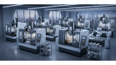
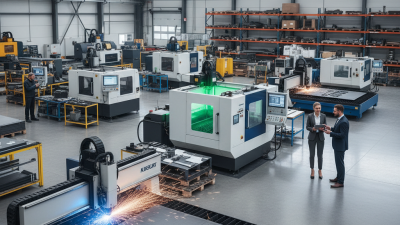
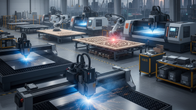
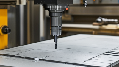
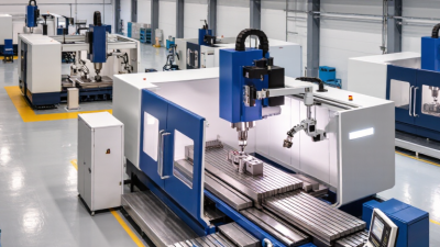
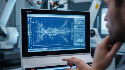
A cnc cutting machine uses computer instructions to remove material with controlled speed and accuracy. It can cut wood, plastic, foam, metals, and composite sheets. The machine follows a programmed toolpath instead of relying entirely on manual movement. This makes repeated shapes easier to produce. It also improves consistency across multiple parts.
The process usually begins with a CAD drawing. CAM software converts that design into machine-readable toolpaths. A controller then sends movement commands to the motors. The cutting head travels along programmed X, Y, and Z axes. Depending on the machine, the tool may be a router, laser, plasma torch, or waterjet. Each option suits different materials and thicknesses. For example, a router may leave visible chips around a plywood edge, while a laser can create a narrow, darkened cut.
Small details matter. Operators check the material, secure the workpiece, and select suitable cutting parameters. They also verify the tool’s condition before production. A wrong feed rate can cause rough edges, overheating, or tool damage. The machine is precise, but it is not magically automatic. Programming errors still create real defects. Even experienced users review simulations and test cuts before trusting a full sheet. This guide explains the working principles, main components, advantages, and practical limitations of a cnc cutting machine. It also considers safety and maintenance, because reliable results depend on both software and human judgment. Mistakes happen. Good practice makes them easier to detect.
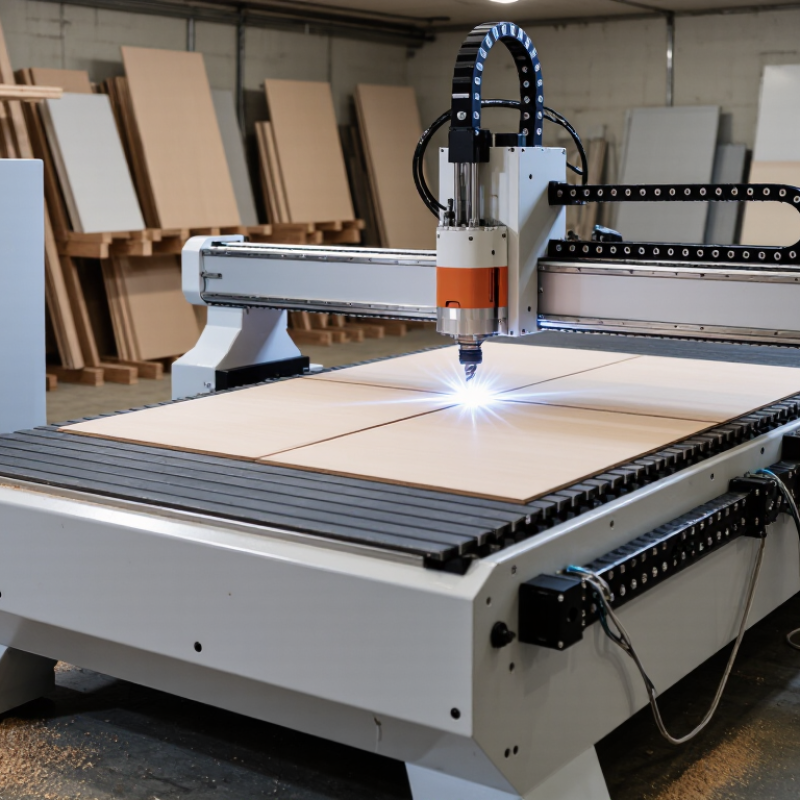
A CNC cutting machine is a computer-controlled tool that cuts, carves, or shapes solid materials. CNC means Computer Numerical Control. The machine follows digital instructions instead of relying only on hand movement. These instructions define the cutting path, speed, depth, and tool direction. Common materials include wood, plastic, foam, aluminum, and mild steel.
The machine has several working parts. A frame supports the material and moving components. Motors guide the cutting head along controlled axes. The cutting head may use a rotating bit, blade, plasma arc, or laser source. An operator prepares a digital drawing and converts it into machine-readable toolpaths. The controller then sends movement commands to each motor. Sensors and limit switches help reduce positioning errors.
Accuracy depends on more than software. Material thickness, tool sharpness, clamping, and dust can change the result. I have found that a secure workpiece often matters as much as a precise file. Small setup mistakes can create visible grooves or uneven edges. It is not magic. The machine still needs inspection, maintenance, and a trained operator. Sometimes the first cut exposes an overlooked detail, such as an incorrect depth or weak support beneath the sheet. That failure is useful, but only if the operator checks the process carefully.
A CNC cutting machine converts digital instructions into controlled physical movement. Its main parts must work together with little room for error. The frame supports the machine and reduces vibration during cutting. A flat worktable holds the sheet, board, or plate in position. Some tables use vacuum zones, while others use clamps or pins.
The controller acts as the machine’s decision center. It reads programmed coordinates and sends signals to the drive system. Motors then move the cutting head along the X, Y, and Z axes. Linear guides and lead screws help maintain accurate movement. Small gaps, dust, or poor lubrication can create visible cutting errors. They are easy to overlook.
The cutting head depends on the material and process. A spindle removes material with a rotating tool, while other systems use heat or focused energy. Sensors may monitor position, temperature, or tool height. Software prepares the design and controls cutting speed, depth, and path order. In practical workshop testing, operators should check tool alignment before starting a full sheet. A short test cut can reveal problems early. The dust collection system also matters, especially when cutting wood or composites. It protects visibility and keeps debris away from moving components. Safety guards and emergency controls provide another layer of protection, although they cannot replace careful setup.
| Main Part | Primary Function | How It Works | Common Configurations | Important Operating Data |
|---|---|---|---|---|
| CNC Controller | Interprets the digital cutting program and coordinates machine movement. | It converts programmed tool paths and cutting commands into electrical signals for the drive motors, spindle, torch, or other cutting head. | Computer-based controller, embedded controller, or industrial control panel. | Typical functions include coordinate control, feed-rate control, tool-path execution, emergency-stop monitoring, and program storage. |
| Machine Frame and Gantry | Supports the worktable, moving assemblies, and cutting head. | A rigid frame limits vibration and keeps the cutting head aligned while the gantry moves along one or more axes. | Fixed gantry, moving gantry, bridge-style, or enclosed structure. | Steel or cast structures are commonly used because stiffness and mass help improve cut stability and dimensional accuracy. |
| Cutting Head | Applies the cutting energy or mechanical force to the workpiece. | The head follows the programmed path while using a rotating tool, focused laser beam, plasma arc, waterjet, or another cutting method. | Milling spindle, laser head, plasma torch, oxy-fuel torch, or abrasive waterjet head. | The suitable head depends on material type, thickness, required edge quality, heat sensitivity, and production speed. |
| Spindle and Tool Holder | Rotates a cutting tool for mechanical material removal. | The motor drives the spindle, which holds the tool and removes material through controlled cutting forces. | Collet-based holders, automatic tool changers, and air- or liquid-cooled spindles. | Wood, plastic, and aluminum routing often uses high rotational speeds; tool speed and feed rate must match the tool diameter and material. |
| Drive Motors | Move the cutting head, gantry, or worktable along the programmed axes. | The controller sends position and speed commands to stepper or servo motors connected to the transmission system. | Stepper motors for simpler systems; servo motors for higher speed, feedback, and dynamic accuracy. | Motor selection depends on axis load, acceleration, travel speed, resolution, and required positioning performance. |
| Transmission System | Transfers motor rotation into controlled linear motion. | Lead screws, ball screws, or rack-and-pinion mechanisms convert rotary motion into movement along the X, Y, and Z axes. | Ball screws for precise linear positioning; rack-and-pinion systems for longer travel distances. | Backlash, lubrication, pitch accuracy, and mechanical alignment directly affect dimensional accuracy. |
| Linear Guides and Bearings | Guide axis movement smoothly and maintain alignment. | Rolling or sliding bearing assemblies constrain motion to the intended axis while reducing friction and unwanted movement. | Profile linear rails, round rails, guide blocks, and precision bearing assemblies. | Clean guide surfaces, correct preload, and regular lubrication help reduce vibration and positional error. |
| Worktable and Material Hold-Down | Supports and secures the material during cutting. | Clamps, vacuum pressure, fixtures, or sacrificial boards prevent the workpiece from shifting under cutting forces. | T-slot table, vacuum table, slat bed, honeycomb bed, or fixture-based table. | The table type should match the material, workpiece size, cutting process, and need for chip or heat removal. |
| Position Sensors and Limit Switches | Provide reference positions and protect the machine from overtravel. | Sensors detect axis limits or home positions and send status signals to the controller. | Mechanical switches, proximity sensors, optical sensors, and encoder feedback. | Homing establishes a repeatable machine reference before cutting and improves setup consistency. |
| CAD/CAM Software | Creates geometry, cutting paths, and machine-readable instructions. | A drawing is converted into tool paths, then post-processed into numerical control code for the machine controller. | 2D profile cutting, 2.5D pocketing, 3D surface machining, and nesting workflows. | Key parameters include tool diameter, cutting depth, feed rate, spindle speed, pierce settings, and cut order. |
| Power and Motion Electronics | Supplies and regulates electrical power for the controller, motors, and cutting system. | Power supplies, motor drives, relays, and safety circuits distribute controlled electrical energy to machine components. | Single-phase or three-phase systems, depending on machine size and cutting technology. | Electrical protection commonly includes fuses, circuit breakers, grounding, emergency stops, and overload protection. |
| Cooling, Lubrication, and Extraction | Controls heat, removes chips or fumes, and protects machine components. | Coolant, compressed air, mist systems, dust collectors, or fume extraction remove heat and cutting by-products. | Flood cooling, air cooling, mist cooling, chip extraction, or dedicated fume extraction. | The system required depends on the cutting tool, workpiece material, heat generation, and type of waste produced. |
| Safety Enclosure and Emergency Stop | Reduces exposure to moving parts, sparks, chips, laser radiation, fumes, and cutting debris. | Interlocks and emergency-stop circuits can interrupt machine motion or cutting energy when an unsafe condition is detected. | Full enclosure, partial guarding, light curtains, access-door interlocks, and emergency-stop buttons. | Safety requirements vary by cutting method; operators should follow applicable local machine-safety standards and procedures. |
Note: Operating specifications vary according to machine design, cutting technology, material, tool selection, and programmed parameters.
A CNC cutting machine turns a digital drawing into controlled physical movement. The process usually begins with a CAD file containing exact lines, curves, holes, and dimensions. A CAM program then reads this design and creates toolpaths for the cutter. These paths define where the tool travels, how deep it moves, and how quickly it cuts.
The software converts those instructions into machine code, often called G-code. Each command controls movement along the X, Y, or Z axis. Some commands also adjust spindle speed, cutting depth, or coolant flow. Before cutting, an operator checks the material size and sets the work origin. A small error here can shift every feature on the sheet.
The machine follows the code step by step. A router, blade, laser, or milling tool removes or separates material along the programmed path. Cutting direction matters. So does tool diameter. CAM software compensates for the tool’s width, but the setting must match the actual tool. Test cuts are useful. They expose mistakes early.
In practice, digital preparation is not always perfect. A drawing may contain an open contour, an incorrect scale, or an unrealistic corner. I have found that simulation catches many problems, but not all of them. Material grain, vibration, and tool wear can still change the result. Careful inspection remains part of the process.
A CNC cutting machine follows digital instructions to remove material with controlled movement. The process begins with a CAD drawing that defines the part’s shape, holes, and dimensions. An operator then prepares the design in CAM software and creates a toolpath. This path tells the machine where to move, how fast to travel, and how deeply to cut.
The operator selects a suitable tool and secures the material firmly on the worktable. Loose material can shift and ruin an otherwise accurate job. Machine coordinates are then set by locating the workpiece zero point. Some workshops use a touch probe, while others rely on careful manual measurement. The program is checked for unsafe movements before cutting starts. A simulation helps, but it cannot replace practical judgment.
During cutting, the controller reads each instruction and moves the tool along several axes. The spindle removes small amounts of material with every pass. Coolant or air may control heat and clear chips, depending on the material. The operator watches for unusual noise, vibration, or excess heat. Small adjustments are sometimes necessary. A perfect first pass is not guaranteed. After machining, the part is measured with calipers or gauges. Edges may need deburring, and dimensions are compared with the original drawing. This inspection step often reveals tool wear, setup errors, or an overly optimistic feed rate.
A CNC cutting machine converts digital geometry into controlled tool movement. Its controller coordinates axes, speed, and cutting power. The method matters more than the word “CNC.”
Laser cutting concentrates heat into a narrow kerf, making it suitable for sheet metal, signage, and fine profiles. Thermal distortion remains a risk.
Grand View Research’s CNC machine market report estimated the global market at about USD 83.6 billion in 2022. The figure supports investment, but it does not guarantee better cutting.
Plasma cutting uses an electrically heated gas stream. It suits carbon steel, stainless steel, and aluminum plates, especially in structural fabrication. It is fast, yet its heat-affected zone may require cleanup.
Waterjet cutting uses high-pressure water with abrasive mineral particles. It avoids a large heat-affected zone. Fabricators use it for stone, glass, composites, and heat-sensitive alloys.
World Steel Association data reported about 1.88 billion tonnes of global crude steel production in 2024. That scale helps explain plasma’s industrial relevance, although thickness and operating cost change the decision.
CNC routers and milling cutters remove material mechanically. Routers handle wood, plastics, foam, and softer composites. Mills provide tighter control for metal parts and drilled features.
Cutting tests should check kerf width, edge squareness, burrs, and repeatability. Reports from MarketsandMarkets project continued CNC equipment growth, but forecasts vary by region and definition. That uncertainty deserves attention.
A low-cost process may create slower finishing work. Good selection begins with material, thickness, tolerance, volume, and surface-quality requirements.