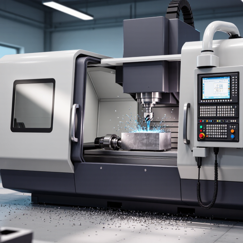
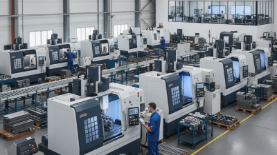
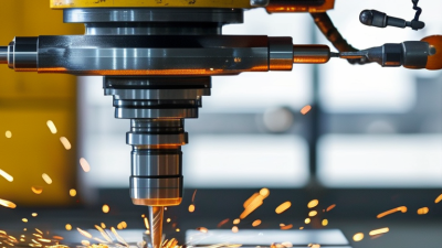
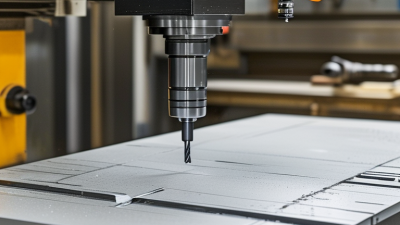
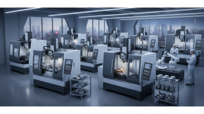
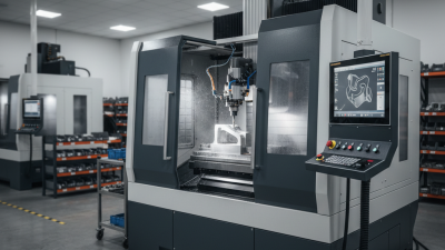
A machining center is a computer-controlled machine tool designed to perform several cutting operations in one setup. Unlike a basic milling machine, it can often mill, drill, tap, bore, and ream without moving the workpiece. That matters because every repositioning can introduce small alignment errors. In a typical workshop, a metal block is clamped to the table, a cutting tool enters the spindle, and programmed movements shape the part along controlled axes. The result may look simple. It is not.
The machine’s control system converts digital instructions into precise movements. Servo motors guide the table, saddle, or spindle, while sensors help maintain position and monitor operation. An automatic tool changer selects different cutters from a tool magazine. Coolant flows across the cutting zone, carrying heat and chips away from the workpiece. Probing systems can check tool length, stock position, and finished dimensions. Small details matter here. A worn tool, loose fixture, or incorrect offset can ruin an expensive component.
Operating a machining center requires more than loading a program. Skilled machinists review cutting speeds, feeds, workholding, tool paths, and material behavior before production begins. They also inspect the first part instead of trusting the screen alone. That habit is important. Even a well-designed process can fail when real conditions differ from the model. Machine accuracy, maintenance history, operator judgment, and measurement results all influence the final outcome. Understanding how these elements work together makes machining centers easier to select, operate, and improve.
A machining center is a computer-controlled machine tool designed to perform several cutting operations in one setup. It commonly mills, drills, taps, and contours metal or engineered plastics. The machine follows programmed coordinates while a spindle rotates the cutting tool. An automatic tool changer selects different tools from a storage magazine.
That sounds simple. It is not.
What makes a machining center different is its ability to combine operations without moving the workpiece between separate machines. A rigid table holds the material, while controlled axes guide the cutter along precise paths. This reduces repeated alignment work and can improve consistency across many parts. In daily shop use, the biggest advantage is often time saved during setup, not cutting speed alone. A well-planned fixture and correctly measured tools still matter greatly.
Some machining centers use three axes, while others add rotary or tilting axes. Extra axes can reach angled surfaces and reduce manual repositioning. However, more movement also creates more opportunities for programming errors and collisions. The machine cannot correct poor drawings, weak workholding, or a damaged cutter. Operators check tool offsets, coolant flow, spindle load, and the first finished part before continuing production. In my view, calling a machining center “fully automatic” is misleading. Human judgment remains essential, especially when a part has thin walls, deep pockets, or tight tolerances.
A machining center combines a rigid machine structure, a motor-driven spindle, and computer-controlled movements. Its main components work together to remove material accurately from a secured workpiece. The base supports the machine, while the column resists cutting forces. A worktable holds the fixture and part. The spindle rotates the cutting tool at a controlled speed. An automatic tool changer selects different tools during one program. This reduces manual handling and keeps production consistent.
The primary linear axes are X, Y, and Z. X usually moves the table left and right. Y controls front-to-back movement. Z changes the tool’s height relative to the workpiece. Their combined movement creates precise three-dimensional cuts. Some centers also include rotary axes. A-axis rotation occurs around X, B-axis around Y, and C-axis around Z. These axes can tilt or rotate a part, allowing access to angled faces without repeated setup.
The control unit interprets programmed coordinates and controls each axis through feedback systems. Encoders compare commanded movement with actual movement. Coolant carries heat and chips away from the cutting zone. An enclosure protects the operator and contains splashing fluid. In practice, accuracy depends on more than the controller. Tool wear, thermal expansion, fixture alignment, and poor chip evacuation can change results. I always verify work offsets with a probe or indicator. Small errors matter. Even a well-designed setup can need correction after the first part.
Representative travel of the primary linear axes in a 3-axis machining center
X, Y, and Z axes provide three linear degrees of freedom. The X-axis commonly controls left-to-right table movement, the Y-axis controls front-to-back movement, and the Z-axis controls vertical movement through the spindle or tool head.
The representative values shown are typical engineering-scale examples for a general 3-axis machining center. Actual travel depends on the machine design, work envelope, tooling requirements, and application.
A machining center performs cutting operations by coordinating a spindle, cutting tool, workpiece, and control system. The operator secures the material on the table and sets its work coordinates. The machine then moves the tool along programmed X, Y, and Z axes.
The spindle rotates the tool at a selected speed. Feed motion pushes the cutting edges through the material at a controlled rate. A milling cutter may remove a broad surface, while an end mill creates pockets, slots, or profiles. Drills produce holes, and reamers improve their size and finish. Small changes matter. Excessive feed can break the tool, while low feed may create heat and poor chip formation.
Cutting fluid can cool the tool and carry chips away. However, it cannot correct an unsuitable cutting speed or a poorly clamped workpiece. Experienced machinists check the first part carefully, measuring dimensions with calibrated instruments. They also inspect the tool for wear, because a worn edge can leave burrs or alter the final size. Tool changes may occur automatically through a controlled tool magazine, reducing setup time between operations.
The process is precise, but not perfect. Material hardness, vibration, and thermal expansion can affect results. I have found that a successful program still needs observation on the shop floor. A simulation may look clean. Real chips can behave differently. Careful adjustment of speed, feed, depth of cut, and coolant flow keeps cutting stable and protects the finished surface.
A machining center is a computer-controlled machine that performs several cutting operations in one setup. It can mill, drill, tap, and sometimes ream metal or plastic parts. The spindle holds a cutting tool, while programmed axes move the tool or workpiece along precise paths. Tool changes happen automatically. Setup quality still matters.
Vertical machining centers are common in job shops and maintenance departments. Their spindle points downward, giving operators clear access to the work area. They suit plates, housings, brackets, and general three-axis work. Horizontal machining centers place the spindle sideways. This arrangement improves chip removal and often supports pallet systems for higher production rates. It also reaches several faces with fewer setups.
Five-axis machining centers add rotary movement to linear travel. They can cut curved surfaces, impellers, molds, and complex aerospace components more efficiently. Gantry-style machines provide a large working envelope for heavy or oversized parts. Each configuration has trade-offs. A five-axis machine may reduce fixtures but demands stronger programming and verification. A vertical machine may appear simpler, yet poor workholding can still ruin accuracy. In practice, the best choice depends on part geometry, batch size, material, tolerance, and operator skill. Small details matter, including spindle power, table travel, coolant delivery, probing, and chip management.
A machining center is a computer-controlled machine that cuts, drills, taps, and finishes metal parts. Its spindle holds a cutting tool, while linear axes move the workpiece with measured precision. An automatic tool changer selects different cutters during one program. Small details matter. Coolant controls heat, chips, and tool wear around the cutting zone.
These machines serve aerospace, medical, energy, automotive, and general engineering applications. They produce housings, brackets, molds, and complex structural parts. Their main benefit is fewer setups, which can improve repeatability and reduce handling time. Deloitte’s 2024 Smart Manufacturing Survey found that 86% of manufacturing leaders expect smart production systems to remain essential for competitiveness. Machining centers support this shift through in-process monitoring, digital programs, and connected production data.
Operating performance depends on more than machine speed. Operators must match feeds and speeds to material, tool geometry, and cutting depth. Poor fixturing can waste the accuracy gained from a high-quality machine. Tool life also changes with coolant concentration and chip evacuation. The International Federation of Robotics reported 541,302 industrial robot installations worldwide in 2023, showing the wider movement toward automated production. Still, automation is not automatically efficient. A claimed 30% cycle-time improvement may disappear when programming, inspection, and maintenance are included. Practical trials should measure total part cost, not spindle time alone.
| Dimension | Machining Center Type | How It Works | Typical Applications | Key Benefits | Typical Capability | Operating Considerations |
|---|---|---|---|---|---|---|
| Machine Configuration | Vertical Machining Center | The spindle is oriented vertically and moves a rotating cutting tool through programmed X, Y, and Z axes. The workpiece is normally secured on a horizontal table. | General prismatic parts, plates, brackets, fixtures, molds, housings, and prototypes. | Good visibility, straightforward workholding, broad tooling compatibility, and relatively simple setup. | Commonly available with 3 linear axes; rotary tables can add a fourth axis or more. | Chip evacuation may be less effective in deep pockets. Tool reach, fixture height, and spindle clearance must be checked. |
| Machine Configuration | Horizontal Machining Center | The spindle is oriented horizontally, allowing the tool to approach the workpiece from the side. Many machines use a pallet system to position multiple faces of a part. | High-volume production of housings, engine components, transmission parts, and complex multi-face components. | Improved chip removal, efficient multi-face machining, reduced refixturing, and strong production throughput. | Frequently configured with 4-axis or 5-axis indexing through a rotary table or workholding system. | Higher initial cost and more demanding workholding, tool management, programming, and maintenance requirements. |
| Machine Configuration | 5-Axis Machining Center | Three linear axes are combined with two rotary axes, allowing the cutting tool or workpiece to be tilted and repositioned during machining. | Turbine blades, impellers, aerospace structures, medical components, complex molds, and parts with difficult-to-reach surfaces. | Fewer setups, shorter tools, better access to angled surfaces, and improved dimensional consistency across multiple features. | Can machine several faces or complex contours in one setup, subject to machine travel and collision limits. | Requires advanced post-processing, collision checking, careful tool orientation, and experienced programming. |
| Core Operating Principle | Computer Numerical Control | A CNC controller interprets programmed toolpaths and coordinates spindle speed, axis movement, feed rate, coolant, and auxiliary functions. | Repeatable production, automated contouring, drilling, tapping, boring, pocketing, and profile milling. | Consistent motion, repeatable part production, automated cycle execution, and reduced dependence on manual handwheel operations. | Positioning accuracy and repeatability vary by machine class, calibration, thermal condition, and maintenance state. | Programs must be verified for work offsets, tool lengths, spindle direction, feed rates, clearances, and safe startup conditions. |
| Tool Management | Automatic Tool Changer | The machine selects tools from a magazine and exchanges them with the spindle according to commands in the CNC program. | Multi-operation parts requiring milling, drilling, tapping, reaming, chamfering, and boring in one cycle. | Reduces manual tool changes, shortens cycle interruptions, and supports unattended or semi-unattended operation. | Magazine capacity varies widely; common systems may hold several dozen tools, while production systems can hold more. | Tool pockets, pull studs, taper surfaces, and tool-length data require regular inspection and management. |
| Material Compatibility | Metals and Engineering Materials | Material is removed by rotating cutters selected for the workpiece hardness, thermal behavior, machinability, and required surface finish. | Aluminum alloys, steels, stainless steels, cast iron, titanium alloys, copper alloys, plastics, and selected composites. | A single platform can support a broad range of components when appropriate tooling and cutting parameters are used. | Cutting performance depends on spindle power, torque, rigidity, tool geometry, coolant, and chip-control strategy. | Hard or heat-resistant materials generally require lower cutting speeds, rigid setups, suitable coatings, and effective heat control. |
| Common Operations | Milling, Drilling, Tapping, and Boring | The spindle rotates a tool while controlled axis movements create flat surfaces, pockets, holes, threads, slots, and contoured profiles. | Part faces, bolt patterns, threaded holes, keyways, pockets, bosses, ribs, and precision bores. | Combines multiple operations in one setup and can reduce transfer errors between separate machines. | Operation quality is influenced by tool runout, workholding rigidity, tool deflection, coolant delivery, and cutting parameters. | Drilling and tapping require correct hole preparation, synchronization, tool selection, and chip evacuation. |
| Production Strategy | High-Mix or High-Volume Production | Programs, tools, fixtures, and work offsets are standardized or reused to produce batches with controlled process conditions. | Contract manufacturing, repeat production, replacement parts, industrial equipment, and precision component manufacturing. | Supports repeatability, shorter setup times, predictable scheduling, and integration with inspection or pallet systems. | Productivity is affected by spindle utilization, cutting time, tool-change time, setup time, and material handling. | Stable workholding, documented setups, tool-life monitoring, and preventive maintenance are essential for consistent output. |
| Accuracy and Quality | Dimensional Control | Encoders, calibrated axes, rigid machine structures, controlled tool offsets, and inspection methods help maintain programmed dimensions. | Precision holes, mating surfaces, bearing seats, alignment features, and components requiring repeatable tolerances. | Better repeatability than many manual processes and reduced variation when the process is properly controlled. | Tolerance capability is application-specific and can range from general machining tolerances to much tighter values under controlled conditions. | Thermal growth, vibration, tool wear, machine geometry, measurement uncertainty, and fixture movement must be managed. |
| Workholding | Vise, Fixture, Chuck, or Pallet System | The workholding device locates and restrains the part while providing access for the cutting tool and maintaining repeatable positioning. | Vises for prismatic parts, fixtures for repeat production, chucks for rotational work, and pallets for automated loading. | Secure workholding improves accuracy, reduces vibration, and enables consistent part location between cycles. | Fixture design must account for clamping force, part distortion, tool access, datum control, and chip clearance. | Excessive clamping force can deform thin parts. Poor access or unsupported areas can cause chatter and tool deflection. |
| Coolant and Chip Control | Flood, Through-Tool, or Minimum-Quantity Lubrication | Coolant or lubricant removes heat, carries chips away, and reduces friction between the tool and workpiece. | Deep-hole drilling, high-speed milling, difficult materials, production machining, and processes requiring controlled surface finish. | Can extend tool life, improve surface quality, reduce thermal effects, and support more stable cutting. | The required method depends on material, tool geometry, cutting speed, chip load, and hole depth. | Coolant concentration, filtration, bacterial control, mist management, and safe disposal require regular attention. |
| Main Benefits | Automation and Reduced Refixturing | Multiple cutting operations can be completed from a programmed sequence without manually moving the part between separate machines. | Complex components, repeat orders, parts with several machining features, and processes requiring consistent alignment. | Lower setup-related variation, reduced labor for repetitive tasks, improved throughput, and better process traceability. | The greatest gains occur when programs, fixtures, tools, inspection, and material flow are properly integrated. | Automation does not eliminate the need for process planning, operator oversight, inspection, and corrective maintenance. |
| Operating Risk | Collision, Tool Failure, and Workholding Failure | Errors in programming, offsets, setup, or tool condition can cause contact between the tool, fixture, workpiece, or machine structure. | All CNC machining operations, especially first-run programs, deep cavities, complex 5-axis paths, and long-tool applications. | Simulation, single-block verification, dry runs, probing, and controlled setup procedures reduce avoidable failures. | Risk level depends on part complexity, tool length, machine kinematics, fixture layout, and operator experience. | Verify tool offsets, clamp security, clearances, spindle direction, coolant flow, and emergency-stop access before cutting. |
| Maintenance | Preventive Care | Regular cleaning, lubrication, inspection, calibration, and replacement of wear components preserve machine performance. | Daily production environments, precision machining, unattended cycles, and equipment operating under heavy chip or coolant loads. | Helps reduce unplanned downtime, preserve accuracy, improve safety, and extend the useful service life of the machine. | Maintenance intervals depend on machine design, operating hours, environmental conditions, and manufacturer specifications. | Check way lubrication, coolant condition, filters, belts, spindle taper cleanliness, axis backlash, and electrical alarms. |